
Author K.P.Barnsdale ZL3KB March 2020.
Rover 5
Programmable robot kit
Instructions
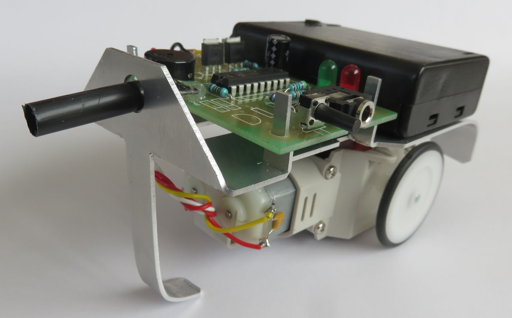
Rover 5 is a programmable robot, utilising two driven wheels capable of forward, left and right motion. The electronics also has a light sensor, push button switch, a speaker and two LEDs. It can be programmed through a Picaxe programming cable using the free PICAXE Editor 6 software, downloadable from Revolution Education found Here
1 Build the Printed Circuit Board (PCB)
Insert and solder components into Printed Circuit Board then add wires and battery
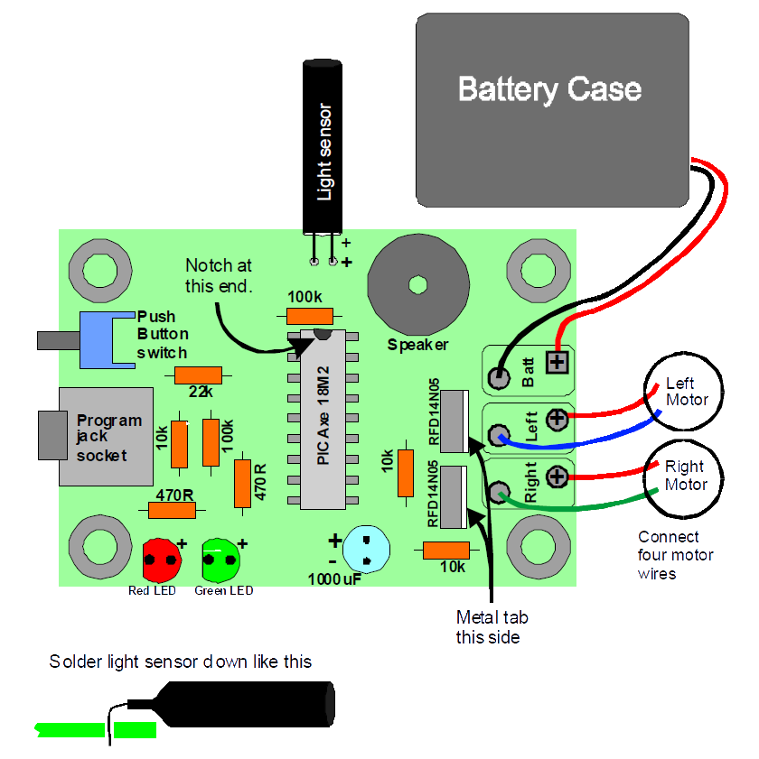
The following components need to be fitted and soldered. Keep all components as low as they can go on the board.
• Insert PICAXE 18M2 microcontroller (the right way around, watch the notch!)
• Add all the resistors. These can go either way around. See colour code below.
• Insert the 1000uF capacitor (long leg = +)
• Insert two LEDs – Red, Green (long leg = +)
• Insert two push button switches legs may need a little straightening
• Insert Light sensor (long leg = +) Keep it low down on the board, see insert.
• Insert the Program Jack socket
• Insert the two RFD14N05 MOSFETS (the right way around, watch the metal tab)
• Insert Speaker. Use the holes that fit the pins, This can go either way around.
• Connect the empty battery pack wires (the right way around, RED is +ve)
• Connect the motor wires (watch the colours)
Many faults can be found with a VISUAL check. Get it visually checked for component orientation, bad solder joints and short circuits. Make sure Picaxe, 1000uF, LEDs, RFD14N06, light sensor are inserted the right way around.
Resistor colour code guide:
10k Brown, Black, Black, Red, Brown
470R Yellow, Violet, Black, Black, Gold
100k Brown, Black, Black, Orange, Brown
22k Red, Red, Orange, Gold
2 Testing the Printed Circuit Board
Once the PCB has been visually checked for bad joints and shorts, test by inserting 3x AA cells, switching on. The LEDs should first show Red and Green for one second. Then listen for a two-note tune, showing Green if the light sensor sees light, and Red if dark. If the button is pressed the sound should stop and the LEDs should continue to respond to the light sensor.
2.1 Modifications
If the light sensor is thought to be too sensitive ie it sees light even in dim areas, the sensitivity can be reduced by reducing the value of the 100k resistor. Try taking it down to 33k if you have a very bright room.
This may be a good opportunity to add any additional components, as detailed in section 4.2
3 Final build
3.1 Prepare the metal chassis
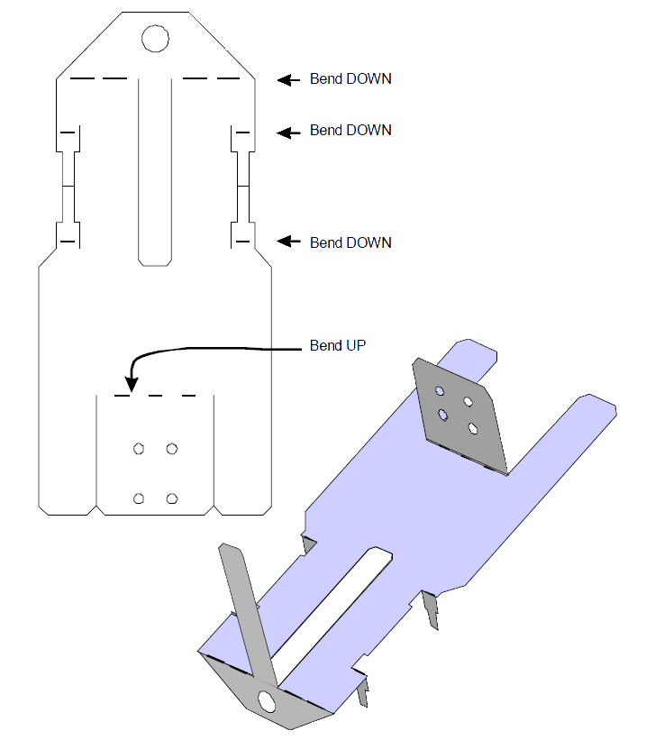
Bend the chassis tabs in the directions shown below:
3.2 Final build onto chassis
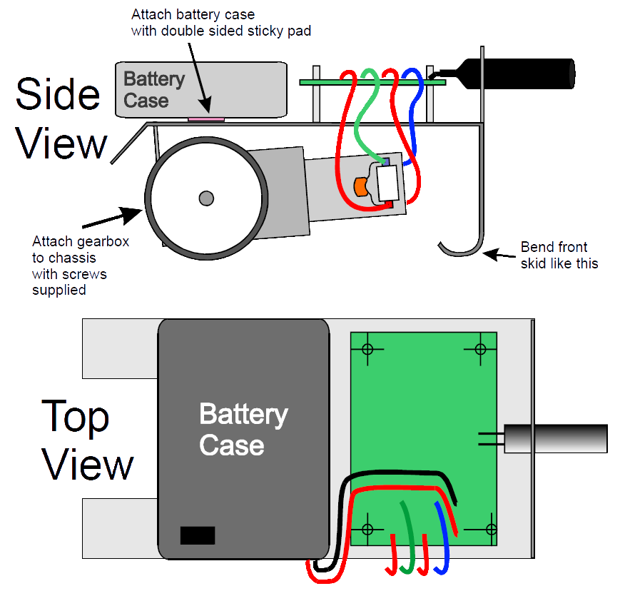
- For safety remove the cells from the battery case
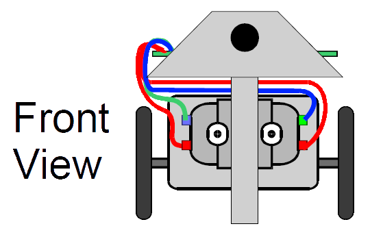
- Attach PCB to top of chassis onto the four metal posts, whilst feeding light sensor through front hole.
- Attach the motor gearbox to the chassis with the supplied screws.
- Attach battery case to top with sticky pads, make sure the switch is uppermost.
3.3 Testing the whole system
Essentially this is the same test as section 2.
On switch on, The LEDs should first show Red and Green for one second. Then listen for a two-note tune, showing Green if the light sensor sees light, and Red if dark. If the button is pressed the sound should stop and the motor should respond to light (Dark = Left, Light = Right). This will make the Rover follow the direction of light in a zig zag motion.
If the button is held down for one second when the Rover is turned on, the speaker will play “Happy Birthday” if the sensor sees light, and “Silent Night” if it is dark.
Programming guide
3.4 Getting ready to program
You will need to obtain a programming cable. See section 4.4
Start your Windows computer running PICAXE Editor version 6.
Connect the Rover5 to your computer using a Picaxe programming cable. Your PC may shows signs of the USB driver being automatically installed if it is the first time.
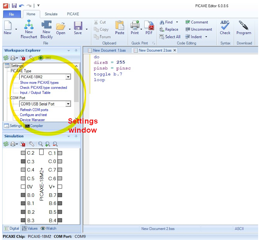
When the PICAXE Editor is open, find the Settings window (see Figure 1), then
• Select PICAXE Type = PICAXE-18M2
• Select COM Port = COM9 (this could be a different number on your PC, look for the one that appears in the list when you plug-in the Rover USB cable)
• Turn on your Rover5 board.
• Click “Check PICAXE type connected” in the Settings window. This should stop the sound of the Rover5 and return a window saying “PASS… “. If this fails, see fault finding section in appendix.
You are now ready to program the Rover 5.
4 Appendix
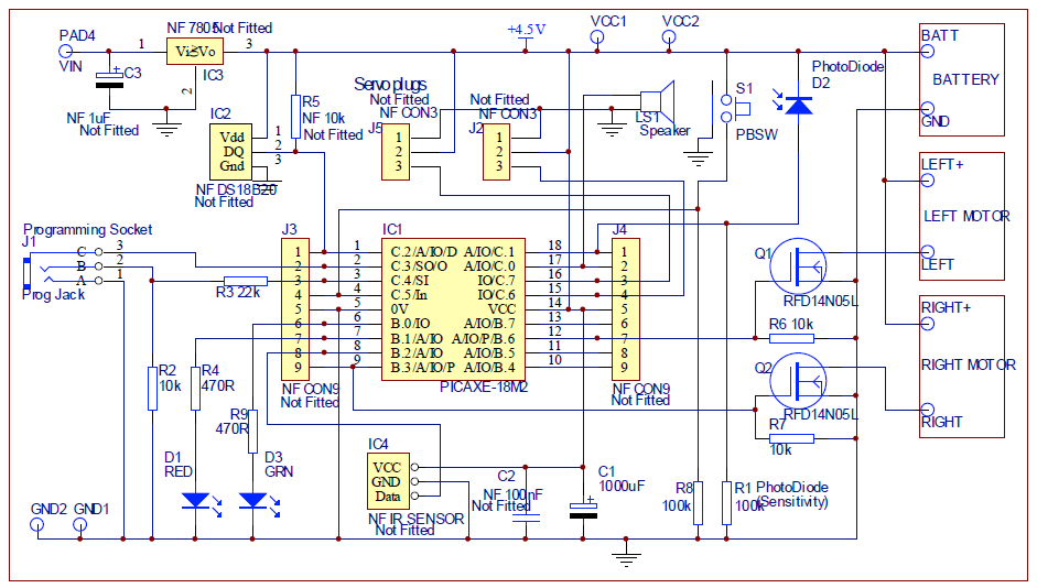
4.1 Circuit diagram of PCB
4.2 Optional parts
The following components are not essential to get the kit running and are not supplied with the kit, but can be added later:
• Temperature sensor IC2 DS18B20 and R5 10k (for logging temperature)
• IR remote control sensor IC4 .
• Regulator IC3, (7805) and C3 1uF – (5V Regulator for running the board from >8V)
• Connectors J3,J4 for fitting a breakout board over the top of the Picaxe.
• RC servos can be connected to plugs J2, J5
• Components C2, 100nF for extra decoupling
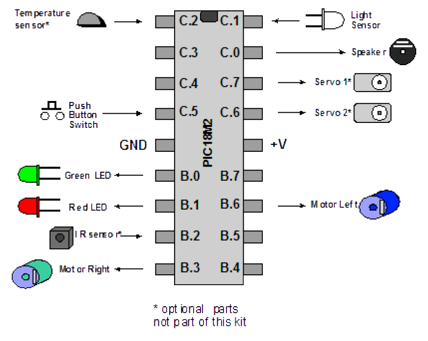
4.3 Pin functions of the Rover5 PICAXE microcontroller
This diagram shows the functions of the Rover5 PICAXE pin numbers which are needed when programming. Note the servos, temperature sensor and IR sensor are not provided in the kit. Two spare ports (c.6, c.7) are provided for future expansion.
Logic sense of inputs
Push button switch activated = logic “1” (high), Switch off = logic “0” (low)
Light sensor sees light = logic “1” (high), Dark = logic “0” (low)
Logic sense of outputs
Motor on = logic “1” (high), Off = logic “0” (low)
LED on = logic “1” (high), Off = logic “0” (low)
4.4 Programming cable
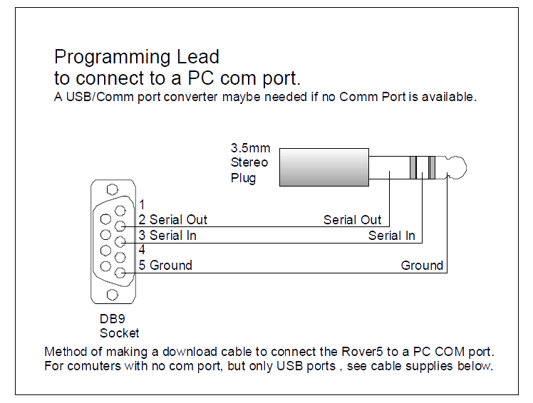
If your PC has a serial Comm port , the cable shown below can be used to program the Rover 5.
5 Pre-programmed code of Rover 5 kit
Note – any words after a semicolon is a ‘comment’ and not part of the coding

5.1 Fault finding guide
Most faults can be cured by double checking the components, soldering or wiring.
This website maybe have some answers to your PICAXE questions
http://www.PICAXE.com/FAQs/Fault-Finding/
5.1.1 Difficulty in finding correct “COM port” number
Make sure the download cable driver has installed OK. The instructions here
http://www.PICAXE.com/Getting-Started/Driver-Installation/ are relevant to this project.
To see which port the programming cable is on, repeatedly plug and unplug the USB cable, and watch which port appears and disappears in the list.
5.1.2 Error: Can’t open port COM(number).
- USB cable not plugged in.
- The wrong COM port selected. Check “Device manager” for the right COM port number. Once installed, plugging in the USB cable should make its COM port number appear in the list.
- Debug or Analogue function has caused Windows to add a new COM port, connected to a non existent device . In “Device manager” check “Mice and other pointing devices” for a Microsoft Serial Ballpoint, then disable (not uninstall) it.
5.1.3 Error: Hardware not found on COM(number)!
- Mostly the problem is the Rover5 has not been turned ON!
- Sometimes caused by an electrical fault on the PCB
- The Debug or Analogue Picaxe function has caused Windows to add a new COM port, connected to a non existent device, then stolen the port from you! In Windows “Device manager” check “Mice and other pointing devices” for a “’Microsoft Serial Ballpoint”, then disable (not uninstall) it.
- This can be caused by the PICAXE being too busy, so turn off the Rover5, start a download of a simple program, when the Picaxe editor program “searches for hardware” (bottom left), quickly turn on the Rover 5.
5.1.4 PICAXE editor freezes
This can happen when using Debug function in the program. Turn off the Rover 5, add a delay such as Pause 100 in the code loop, restart the Rover 5 and reprogram.
5.1.5 Where can I find help on PICAXE commands?
An up to date source is here
PDF of the manual is here
The user forum is here