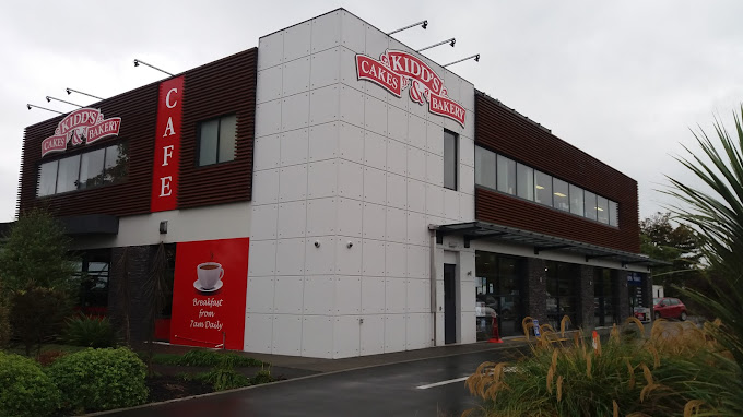
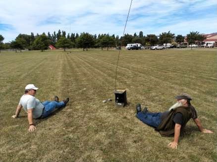
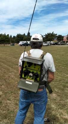
On 24th January, the club held a combined BBQ and antenna measuring day at Agricultural park. In an adjacent park, the ‘Green radio boy’ ZL3KB had setup a reference ¼ wave vertical on 40m to measure the radiated power from his WW2 man packs.

From Rob ZL2IW: We were advised to keep clear of the test range as a body there may change the Radiation characteristics of the tx or receive antenna.
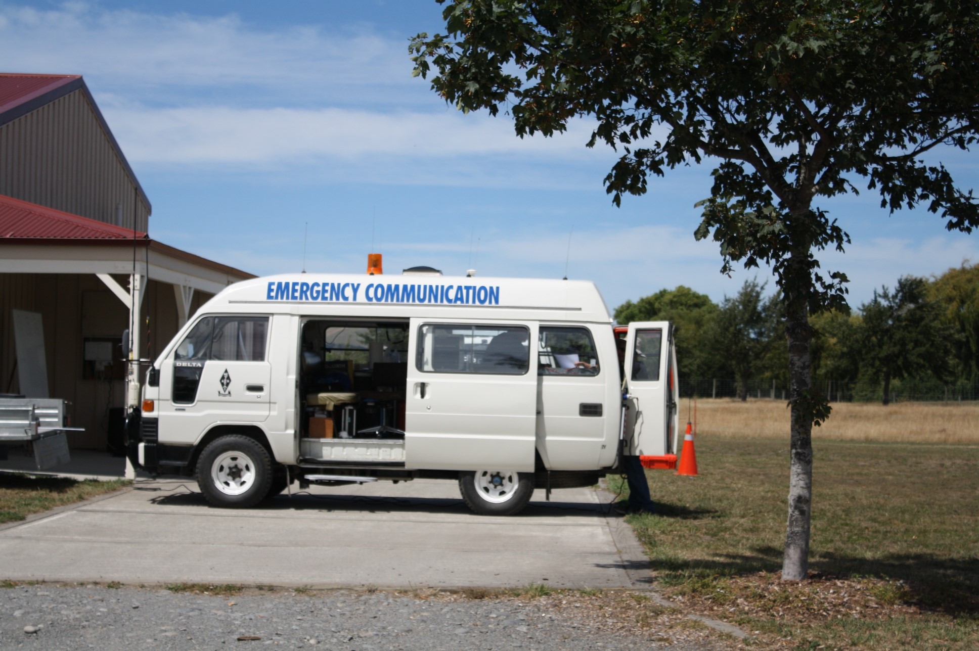
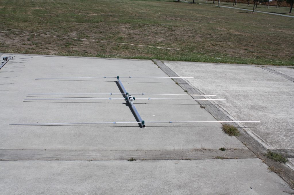
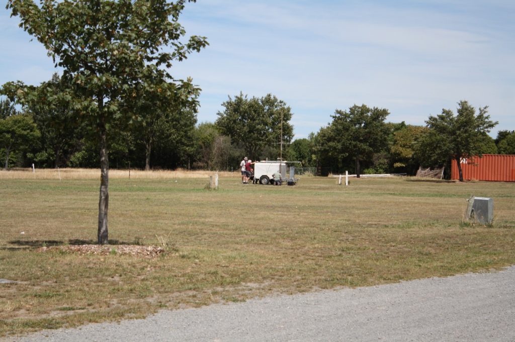
The transmit antennas VHF and UHF were in the cones near the white van which housed the Marconi signal generator. This provided a stable and known input to the transmit antennas. By calibration at the receive end with a test dipole we were able to say something about the overall gain (or loss) of subsequent antennas.
At the receive end the test antenna was mounted on the trailer mast. The mast could be rotated and the azimuth bearing read off a card and pointer arrangement. At each designated bearing the resulting signal was recorded from the spectrum analyser display. Thus creating an azimuth plot of the test antenna characteristics.
Back at the comms van this could be manually input to the computer and thus Ian could generate a plot of the antenna… including something useful about the gain etc of the antenna …
Hi and all the best from Kaye and me, Hopefully you should have a dozen photos of the event… really sorry I didn’t take a heap more… got distracted and failed to realise the import of photo records.

We were advised to keep clear of the test range as a body there may change the Radiation characteristics of the tx or receive antenna. The transmit antennas VHF and UHF were in the cones near the white van which housed the Marconi signal generator. This provided a stable and known input to the transmit antennas. By calibration at the receive end with a test dipole we were able to say something about the overall gain (or loss) of subsequent antennas.

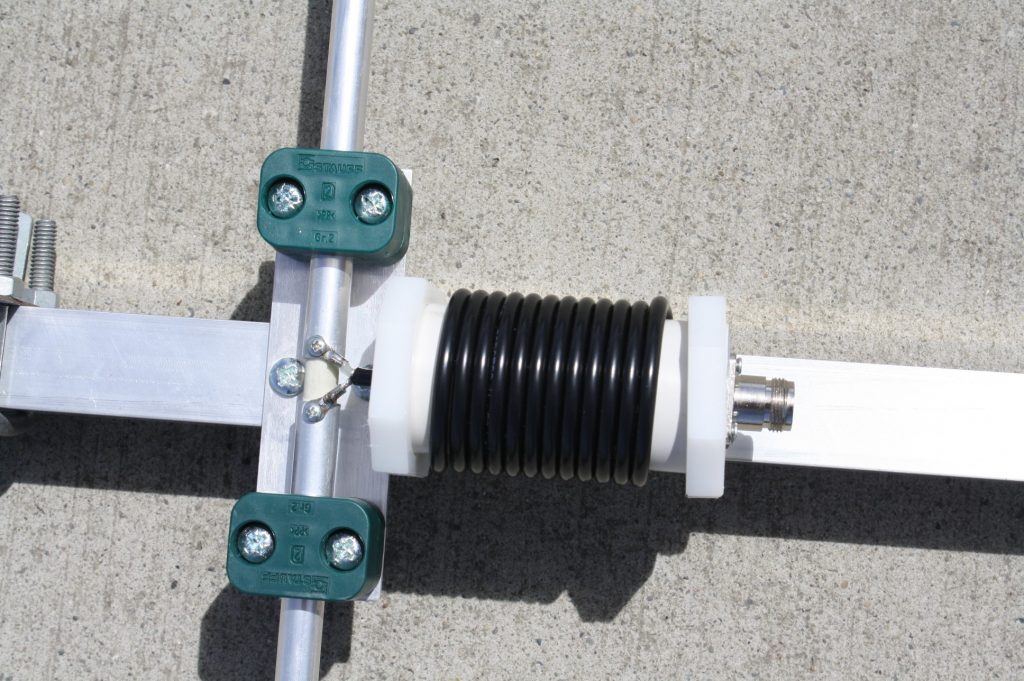
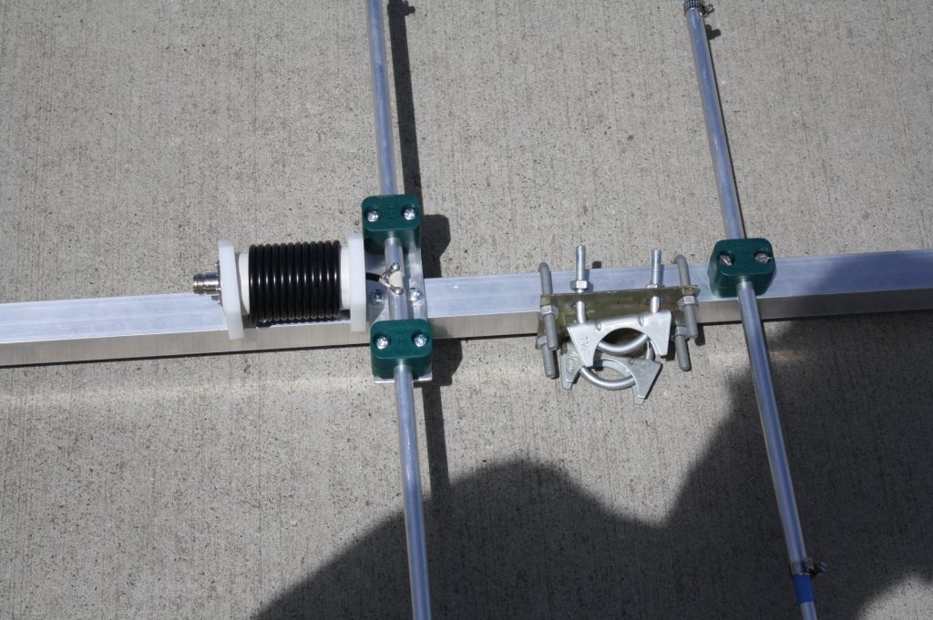
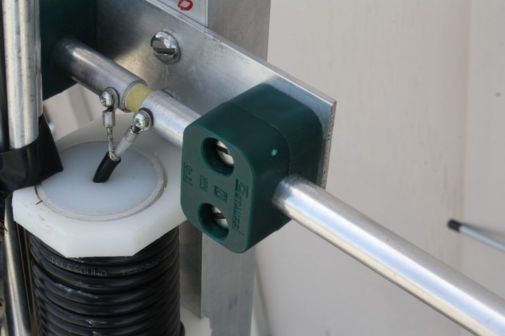
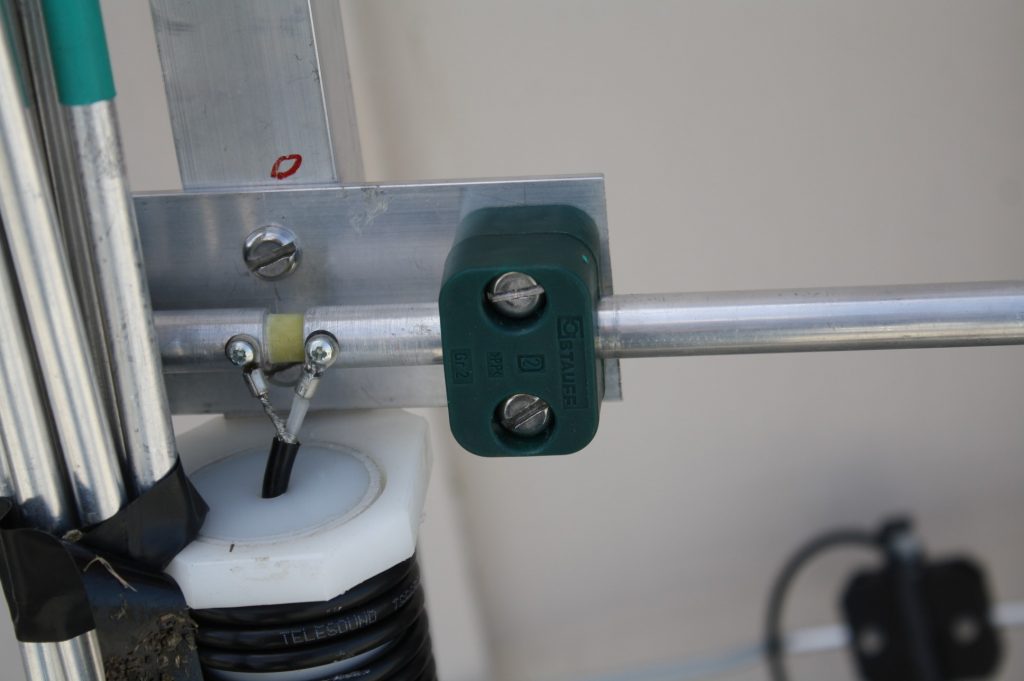

At the receive end the test antenna was mounted on the trailer mast. The mast could be rotated and the azimuth bearing read off a card and pointer arrangement. At each designated bearing the resulting signal was recorded from the spectrum analyser display. Thus creating an azimuth plot of the test antenna characteristics.
Back at the comms van this could be manually input to the computer and thus Ian could generate a plot of the antenna… including something useful about the gain etc of the antenna …
With hindsight I should have taken the camera down to the trailer and photographed the spectrum analyser and the turning display card for the antenna azimuth … oops
Anyway hope these give some flavor to the event.
Some of the other guys there may also have photos and a better explanation of what was going on….
In an adjacent paddock Kelvin set up a reference HF antenna connected to a USB spectrum analyser and PC. This was for testing his man pack radios on 7.1MHz … test distance set to 50 metres and several old radios and their antenna setup were recorded…
A fun day and had a great time chatting with people and playing with radios.
Words & photo’s provided by Rob Zl2IW.