TechnoClub Rover 6 Instructions.
Rover 6.
Programmable robot.
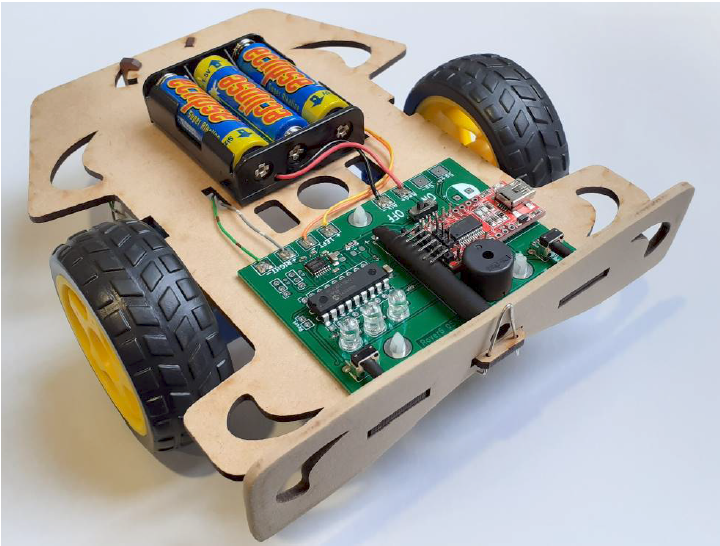
Rover 6 is a programmable robot, utilising two driven wheels capable of forward or backward motion. The electronics also has a light sensor, two bumper sensors, a speaker and three LEDs. It can be programmed through a standard USB cable using the free PICAXE Editor 6 software, downloadable from Revolution Education found on http://www.PICAXE.com/Software
Stage 1: Build the Printed Circuit Board (PCB)
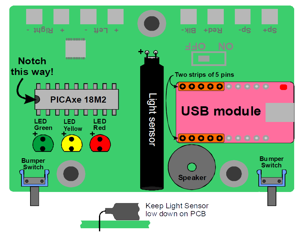
You will see some tiny components have already been placed on the PCB. The following large components need to be fitted and soldered. Keep all components as low as they can go on the board.
- Insert PICAXE 18M2 microcontroller (the right way around, watch the notch!)
- Insert three LEDs – Red, Yellow, Green (long leg = +)
- Insert two bumper switches
- Insert Light sensor (long leg = +) Keep it low down on the board
- Insert USB module
- Insert Speaker. This can go either way around.

Get it checked!
Stage 1 (cont): Testing the Printed Circuit Board
Once the PCB has been checked, start your computer running PICAXE Editor version 6.
Connect the Rover6 to your computer using a mini USB cable, and the USB module red power light should come on. Your PC may shows signs of the USB driver being automatically installed if it is the first time.
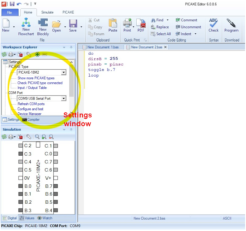
When the PICAXE Editor is open, find the Settings window (see Figure 1), then
• Select PICAXE Type = PICAXE-18M2
• Select COM Port = COM9 (this could be a different number on your PC, look for the one that appears in the list when you plug-in the Rover USB cable)
• Click “Check PICAXE type connected” in the Settings window. This should flash green lights on the Rover6 USB module and return a window saying “PASS… “. If this fails, see fault finding section in appendix.
You are now ready to program the Rover6.
To test all the components you have recently added, type (or copy/paste from this document) the program shown in Appendix 1.3 and click “Program’ button on the top ribbon. Programming is indicated in the lower right corner of the screen, and two green flickering lights on the USB module.
Once this program has been loaded, the speaker should make a note, pushing the left bumper should light the yellow LED, right bumper should light the red LED, and showing light to the light sensor should activate the green LED.
Stage 2 : Build the chassis.
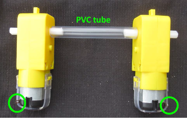
- Connect motor axles together with PVC tube, leave 1mm gap at each end. Get them the right way around! The motor connections are towards the outside.
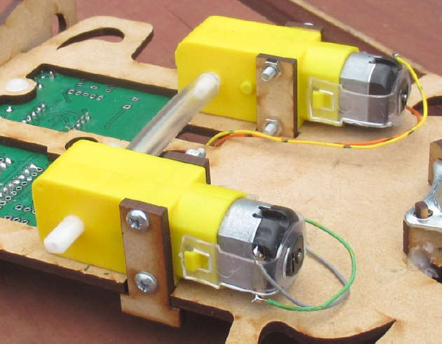
- Using location guides shown in Figure 4 below, attach motors to bottom of chassis with tabs, screws and nuts. Do not fit driving wheels yet!
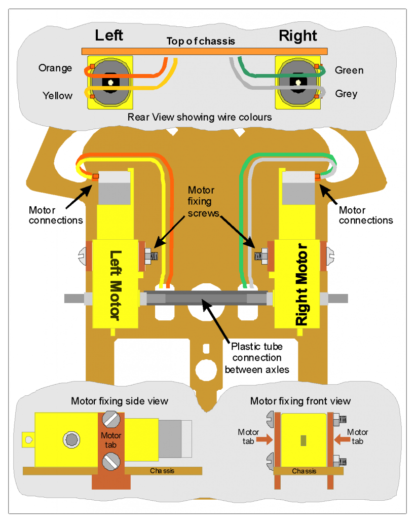
- Solder wires to motors (Orange and yellow, green and grey, 140mm each) using Figure 3 and Figure 4 as a guide.
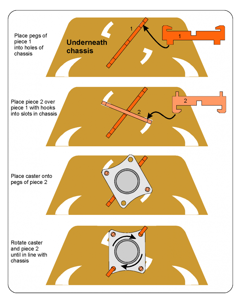
Stage 2 (cont) :
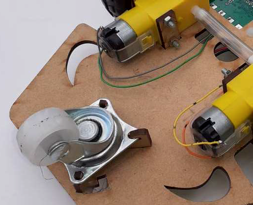
Fit rear caster wheel.
This is fitted on the SAME SIDE as the motors! Follow the instructions below. If the parts are a little loose, a little hot glue can be used underneath to
secure part 2 to the chassis.
Stage 2 (cont) : Fit PCB to chassis.

- Attach battery case to top with hot glue, Velcro or sticky pads, this may need double layer pads.
- Attach PCB to top of chassis with three plastic rivets from below. Add a little hot glue on top to secure them.
- Solder red and black wires of battery to PCB (Red+, Blk-)
- Solder left (Orange-, Yellow+) and right (Green-, Grey+) motor wires to PCB
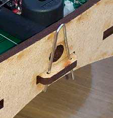
- Attach front bumper to chassis with reshaped paperclip wire, keeping the front light
sensor hole clear

Stage 2 (cont) : testing the whole system.
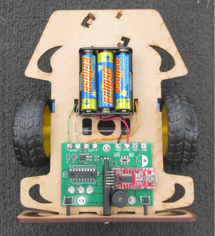
Proceed no further until your wiring has been checked. Assuming we have tested the PCB in the previous stage, all we need to test now is the battery connections and motors.
Firstly, turn off the switch on the PCB, fit the wheels and insert three AA cells into the battery holder.
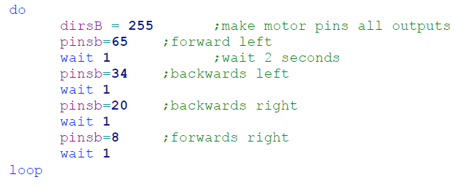
Load the motor test program found in appendix 1.4 . The Rover will be powered by the USB cable, but the battery switch on the PCB will need to be ON to run the motors.
Once the Rover has been programmed, USB cable removed and turned ON it should drive:
- Left forward
- Left backward
- Right backward
- Right forward
If you find any part of this sequence is missing or reversed, check your wiring.
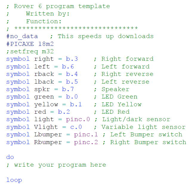
Program template.
The pin functions of the Rover 6 PICAXE micro controller can be found in Figure 9.
To make things easier to program, you can use the template file in appendix 1.1. This can be loaded when starting a fresh program, then “saved as” with a particular name for storage and recall. It assigns names to the Rover 6 functions, in place of pin numbers. For example, when programming the red LED, we can use the name “red” instead of “b.2”.
The green text after the semicolons are “comments” and just for our information, and not part of the program.
The template also has some extra features, such as the skeleton “do / loop” which can be used to make your program a continuous repeating function.
See the PICAXE help files for more information.
1 Appendix
1.1 Rover 6 program template
Program name “Rover6 template.bas”
1.2 Pin functions of the Rover 6 PICAXE microcontroller.
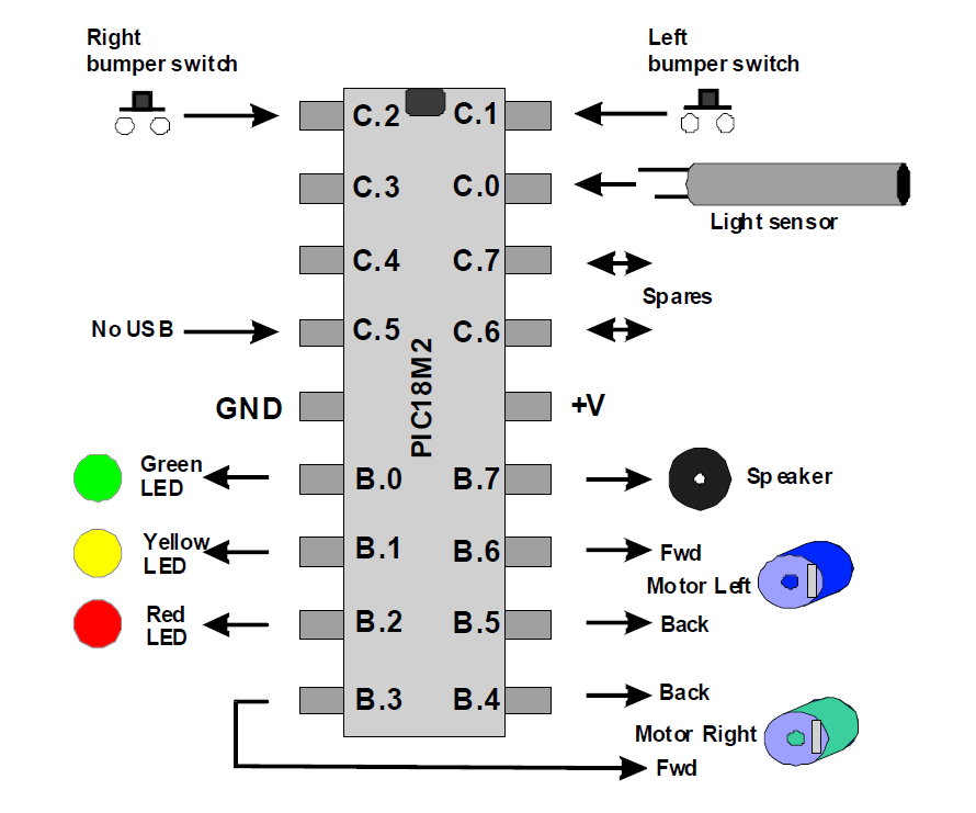
This diagram shows the functions of the Rover6 PICAXE pin numbers (b.2 = red LED etc) which are needed if you do not use our template. Two spare ports (c.6, c.7) are provided for future expansion.
1.2.1 Logic sense of inputs.
Bumper switch pushed = logic “1” (high)
Light sensor sees light = logic “1” (high)
1.2.2 Logic sense of outputs.
Motor on = logic “1” (high)
LED on = logic “1” (high)
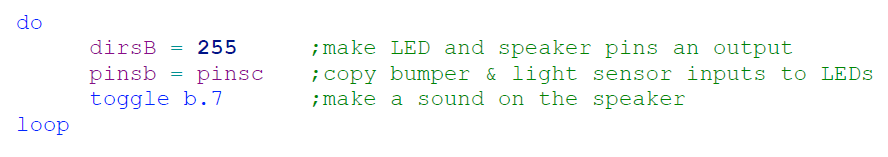
1.3 Initial program to check PCB components.
Copy and paste this program into the PICAXE editor. To keep it as short and simple as possible, this example does not use the template file shown in appendix 1.1, so functions such as speaker appear as pin numbers (b.7) instead of words.
Once this program has been loaded, the speaker should make a note, pushing the left bumper should light the yellow LED, right bumper should light the red LED, and showing light to the light sensor should activate the green LED.
Program name “PCB check.bas”
1.4 Program to check motors and battery connections.
Copy and paste this program into the PICAXE editor . To keep this as simple as possible, this does not use the template file shown in appendix 1.1, so functions such as left motor appears as pin number (b.4) instead of words.
Program name “Motor check.bas”