Attenuator‘s
Signal strength the meters on their radios show the hunters that they are getting close to the hidden transmitter, but as the hunters (hounds) get close to the transmitter (fox), the strong signals make the signal strength meters (S-meter) on the radio is useless.
The closer you get to the transmitter you’re seeking, the tougher it is to find! Some means of reducing the amount of signal that the radio receives becomes necessary.
An attenuator placed in the feedline between your antenna and receiver will diminish the strength of the received signal.
The S-meter can then be used to observe signal strength variations as you proceed closer to the hidden transmitter.
There are basically two types of attenuators active and passive.
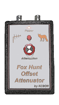
Active Attenuators
Active attenuators make use of active components and thus require a source of power in order to function. The offset attenuator is an example of an active attenuator. Instead of directly attenuating the incoming signal, in offset attenuator works by adjusting the strength of an offset frequency signal.
Plans for other simple active attenuators can be found by searching the Internet.
One disadvantage of offset attenuators is that they require a battery to make them work, so you’ve got to remember to turn them on… and off! Another drawback to most offset attenuator designs is that their attenuation level is not calibrated; so you can never be certain just how much attenuation you’re using.
Because most offset attenuator designs include no filtering between the antenna and the mixer, the attenuator is potentially a very prodigious intermod producer. This can be a real problem when an offset attenuator is used in an area with strong out-of-band signals, such as neighborhoods near broadcast or paging towers.
Note: Avoid transmitting through an offset attenuator. Doing so could possibly destroy the attenuator or harm your radio. If it doesn’t destroy the attenuator, it will almost certainly result in strong out-of-band signals being generated by the mixer in the attenuator.
Below is an example of an offset attenuator made by Martin KE6HTS
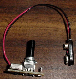
K0OV Offset Attenuator
The offset attenuator modules are on a PC board 3/4″ x 1 1/4″. The kit consists of the circuit board with all the surface mount components soldered in place, and the other parts necessary to complete the unit (diode, potentiometer, crystal, and 9V battery leads.) The surface mount components include all capacitors, resistors, and the voltage regulator.
Parts List
Qty P/N
- 1 PCB w/ SMT components soldered in place
- 1 5K Potentiometer
- 1 Oscillator (2 MHz or 4 MHz)
- 1 1N4148 or 1N914 Diode
- 1 9V Battery Lead
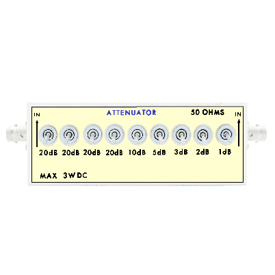
Passive Attenuators
Passive attenuators contain no active components, but inherently impose an absorptive or reflective loss directly to any signal passing through them.
The resistor network attenuator is an example of a passive attenuators.
Most attenuators of this type are operated using a series of switches that select a variety of resistor values. By configuring the switches appropriately, any attenuation level between 1 dB and 80 dB can be selected, in 1-dB steps.
For much of the hunt, a resistor-network attenuator will work quite well. Unlike most offset attenuators, resistor-network attenuators provide accurate, and very repeatable, attenuation settings.
Most passive attenuators will not generate intermod signals that might interfere with your hunting efforts.
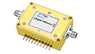
Below is an example of a resistor-network attenuator from a well-known company MFJ Enterprises, founded in 1972 by Martin F. Jue.
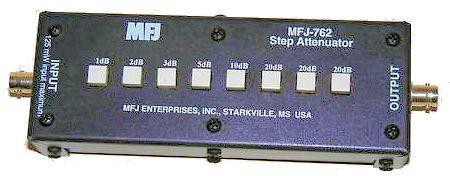
Shown above is the MFJ-792 Step Attenuator that provides up to 81 dB in signal attenuation.
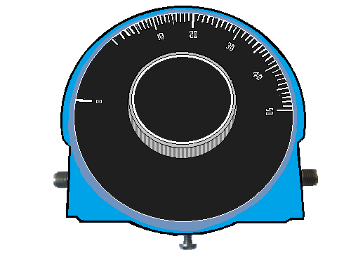
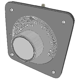
Pueblo West Amateur radio club member Paul, KB0JIT, used this idea as the basis of one of the prototype homebrew attenuators he built (below)
Note: Avomgd transmitting through a resistor-network attenuator. Doing so could destroy the attenuator if it is not designed to handle the transmitter’s output power level.
Fixed Value Passive Attenuators
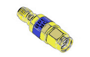
Being able to control the amount of attenuation used is a great feature, but as an alternative, one of more fixed value attenuators can be used if needed. If you have a radio with an SMA or a BNC antenna connector, you might be able to find a variety of fixed value attenuators on online that can connect directly to your radio.
Note: Avoid transmitting through a fixed value attenuator. Doing so could destroy the attenuator and harm your radio if the attenuator is not designed to handle the transmitter’s output power level.
Attenuator Alternatives
Ok, so what are your options if you want to go on a Fox Hunt this weekend and have no attenuator? You might want to try these techniques.
Tune Off Frequency
Try tuning your receiver 5 kHz or more above or below the transmitter’s frequency. This effectively uses the skirts of the IF passband to attenuate the signal and keep you in the hunt. Since you are no longer tuned atop the signal’s carrier, you’ll probably notice that any modulation of the signal will cause the signal strength to appear to jump around. So this is a less-than-ideal substitute for a “real” attenuator.
Rotate Your Antenna
You can attenuate the signal you’re hunting by orienting your antenna so that its angle of polarization is not aligned with the signal’s polarization. For instance: if you hold a yagi antenna so that its elements are aligned vertically, the antenna will be less efficient for hunting a signal that is horizontally polarized. The yagi antenna will pick up the signal more weakly when it is misaligned in that manner, which is just what you want.
Note: The previous three suggestions will help knock the signal strength down so that you can continue to use your receiver and VHF beam antenna. The remaining suggestions will require that you reconfigure your hunting equipment and hunting style.Tune to a Harmonic
If you have a receiver capable of tuning to a multiple of the transmitter’s frequency, try listening to the second or third harmonic. (That’s two times, or three times the transmitter’s frequency.) If you can hear one of the harmonics, you’re getting close. Once you can hear a harmonic, you might switch over to an antenna designed for the harmonic frequency. If you are using a tape measure yagi, shorten the elements by tucking them inside the “X” connectors.
Body Fading
Body fading is a technique that can be used when you’re stuck without better hunting equipment. The technique involves holding the receiver close to your abdomen, and then rotating your body slowly while observing the signal strength indicated by the receiver. If the signal is still too strong, disconnect the antenna. Most reflected signals will not be strong enough for your receiver to pick them up without an antenna. Which means you will be most successful with the body fade technique when you are close enough to the transmitter that you can perform body fade with no antenna connected to the receiver.
Remove the Antenna
Do you think you might be right on top of the transmitter, but you’re not sure? Try this test: disconnect the antenna from your receiver. Do you still hear the signal? If yes, you are getting close to the transmitter. If the signal is still full scale with the antenna disconnected, you may be very close! But be careful. Most handy talkies today have plastic cases, and may pick up the signal without an antenna when you are still some distance from the transmitter.