
Antenna’s
Tape measure beam optimized for radio direction finding (fox hunting)
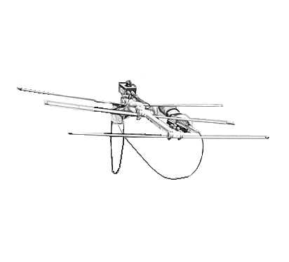
This design exhibits a very clean pattern and is perfect for RDF use. It is a design that can be constructed using only simple hand tools and still perform well. This antenna has one basic idea in mind simplicity.
This is accomplished by the use of steel “Tape measure” elements. The elements fold easily when fitting the antenna into any vehicle or bag for transport, yet still self-supporting. Three elements to keep the boom from getting too long.
For easy of construction PVC pipe and fittings, available any local hardware store, are used for the boom and element supports. The element supports consist of PVC crosses and tees. The elements used are made from1 inch wide steel [tape measure].
The design was aided by a YagiCad software programme written by Paul McMahon VK3DIP.
Performance predicted by YagiCad:
Gain 7.3dB
Front to back Ratio >50dB
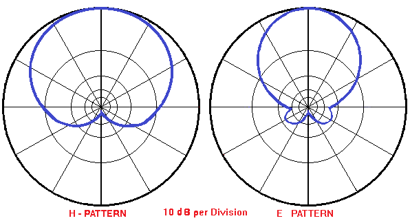
3db beamwidth E= 67.5 degrees & H=110 degrees
Network matching is need to have a low SWR. A Gamma match is unwieldy and not very flexible. The best matching network turns out to be a “hairpin match”. This is simply a 5 inch length of wire that is connected across the feed points of the driven element. The antenna has some capacitive reactance without the matching network. The 5 inch length of wire has just enough inductance to cancel the capacitive reactance. The wire suggested for the hairpin match is enamel insulated 18 gauge solid copper wire. 14 gauge house wire works well, so does a length of 22 gauge hook-up wire. It does not seem to matter if it is stranded or solid, use whatever you have available. This results in a very good match across the two meter band once you have adjusted the distance between the halves of the driven element for minimum SWR (approx. 1”).
Use a pair of shears to cut the tape measure elements to length. An old pair of scissors will probably do as well. No matter how you cut the elements be very careful. Those edges are very sharp and will inflict a nasty cut if you are careless. Use some sandpaper to remove the really sharp edges and burrs resulting from cutting the elements to size. Some vinyl electrical tape on the ends of the elements to protect from getting cut is a good idea. Round the corners of the elements once you cut them. And please wear safety glasses while cutting the elements, those bits of tape measure can be hazardous.
A RG58 coax feedline is connected directly to the driven element. No matter what method you use to attach the feedline, make sure you scrape or sand the paint off the tape measure element where the feedline is attached. Most tape measures have a very durable paint finish designed to stand up to heavy use. You do not want the paint to insulate your feedline connection.
Carefully, solder the feedline to the element halves. Care must be taken since the steel tape measure does not solder easily and since the PVC supports are easily melted. You might want to tin the tape measure elements before mounting them to the PVC cross.
If you decide not to solder to the tape measure elements, there are two other methods that have been used to attach the feedline. One method employs ring terminals on the end of the feedline. The ring terminals are then secured under self-tapping screws which hold the driven element halves. This method does not allow you to tune the antenna by moving the halves of the driven element. 6-32 bolts and nuts could be used if holes are drilled in the elements near the ends. If the bolt heads are placed nearest the PVC fitting, you could secure ring-terminals with nuts and lock washers. Another possibility is to simply slide the ends of the feedline under the driven element hose clamps and tighten the clamps to hold the ends of the coax. This is low-tech, but it works just fine.
Stainless steel hose clamps are used to attach the driven element halves to the PVC cross which acts as its support. This has the added benefit of allowing you to fine tune your antenna for lowest SWR simply by loosening the hose clamps and sliding the halves of the driven element either closer or further apart. By using the dimensions specified, the SWR should be 1:1 when the two elements are spaced approximately 1 inch apart.
1/2 inch hose clamps to attach all the elements are used in this design. Others who have duplicated design have used self-tapping screws to attach the elements to the PVC crosses and tees. Performance is the same using either method. The screws are much less expensive but they do not hold the elements as securely. If you do not use 1/2 inch PVC fittings but instead use 3/4 inch, make sure the hose clamps you buy are large enough to fit.
If you wish a slightly neater looking beam, use the self-tapping screws. If you do not mind spending a few more dollars for the hose clamps, use them instead. You could use screws for the director and reflector, and hose clamps for the driven element. That would give me the best of both methods.
Parts List
- 1 25 foot [8m] 1 inch [25mm] wide steel tape measure
- 1 10 foot [3m] piece of 1/2 inch [25mm] PVC pipe
- 2 3/4 inch PVC Cross connectors
- 2 3/4 inch PVC T connector
- 6 1 1/2 inch [38mm] stainless hose clamps
- 1 5 inch [127mm] piece of 14 ga wire
- 1 length of RG-58 cable, approx 6 foot [2m]
- Solder and Flux
- Electrical Tape
Tools
- Soldering Iron
- Tin Snips
- Wire Cutter
- Screw driver or nut driver
- PVC cutter or fine tooth saw
- Sand paper or Dremel tool with sanding disk
- Ruler or tape measure
Construction:
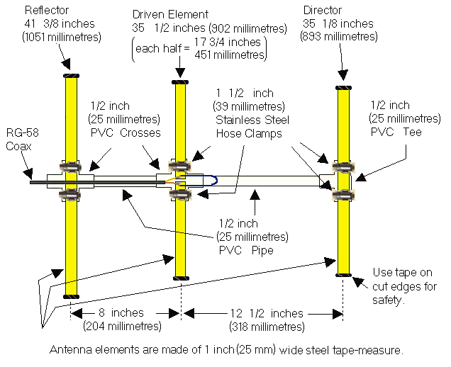
Cut a length of tape measure to 41 3/8 inches [1051mm]. It will be the Reflector element. Cut two lengths of tape measure to 17 3/4 inches [451mm]. These will be used for the Driven element. Cut one length of tape measure to 35 1/8 inches [893mm]. It will be used for the Director. Once you have cut the tape measure to length, round the ends and put vinyl tape on the cut ends to protect yourself from the sharp edges. You will want to scrape or sand off the paint from one end of each of the driven element halves so
If you are planning to solder the feedline to the driven elements it is best to tin the elements first before attaching them to the PVC cross. If you don’t, the PVC will melt as you apply heat to the element. It would be a good idea to also take the time to form the wire used for the hairpin match into a “U” shape with the two legs of the “U” about 3/4 [20mm] inch apart. Tin the ends of the hairpin if you plan on soldering it to the driven element. If you tin 1/4 inch [6mm] of each end of the hairpin it will leave 4 1/2 inches [115mm] to shape into the “U” to make a good electrical connection for the feedline.
You will need to cut two lengths of PVC pipe to use as the boom. One should be cut to 11 1/2 inches [293mm]. It is used to form the boom between the Director and the driven element. The other piece of PVC should be cut to 7 inches. It will be used between the Reflector and the Driven element. Just about any saw will cut through the soft PVC pipe including a hacksaw. When this design was mass produced as a club project, marked the pipe and a portable jig saw to cut the lengths in assembly line fashion. It takes longer to measure the pipe than to actually make the cuts. Since the pipe is available in ten foot lengths, you can make a few beams from a single length. In any case, you might want to cut a few extras lengths for your friends. They will want to duplicate this once they see your completed antenna.
At this time you can pre-assemble the PVC boom, crosses and tee which will support the tape measure elements. The use of any cement or glue will depend on whether the PVC pipe remains secured in the fittings with a friction fit or not.
The hose clamps are stainless steel and have a worm-drive screw which is used to tighten them. They are about 1/2 inch [13mm] wide and are adjustable from 11/16 inch [18] to 1 1/2 inches {38mm] in diameter. Attach the tape measure elements to the PVC fittings as shown in the accompanying drawing. It is normal for the Reflector and Director elements to buckle a bit as it is tightened to the PVC Tee and Cross. You can eliminate this buckle if you use the washers and self-tapping screws to attach these elements instead of the hose clamps. But the beam might not withstand as rough a treatment as much as when hose clamps are used.
How does it perform?
Once you have completed your beam you probably will be interested to see if it performs as well as the computer predicted. The SWR should be less than 2:1 across the entire two meter band. The front-to-back ratio is predicted to be very good with the antenna exhibiting a very deep notch in its pattern towards the rear. The YagiCad program produced these antenna pattern graphs showing the pattern you should expect. If you would like to experiment a bit with this program, the Yagi specification file for this tape measure beam is available for download here (=> insert link here). Simply download the YAGI-CAD program and put the tape measure beam design file in the same directory. You will then be able to experiment with the design.
Note: YagiCad will work with Microsoft Windows up to Windows 10.
Summary
This beam has been used on Fox-Hunts, on mountain tops, at local public service events, outdoors, indoors in attics, just about everywhere. The SWR is typically very close to 1:1 once adjusted. Front to back performance is exactly as predicted. The null in the rear of the pattern is perfect for transmitter hunts. When tested using a sensitive field strength meter and a low powered fox transmitter, full scale readings were seen from a distance of ten feet. With the same field strength meter, pointing the antenna away from the transmitter and move the reflector element to within a few inches of the transmitter antenna and still not see a reading. The flexible elements can take a lot of abuse. Best of all, when on a fox-hunt, this beam is a breeze to get in or out of the car or bag.