Rob ZL3TCM
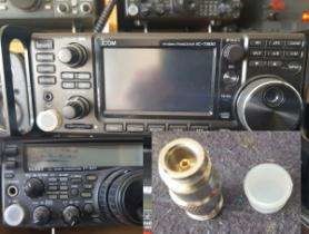
Here’s an idea I have been using for a while , when my rigs are being used for digital modes I normally remove the mic. I simple dust cap is a cover from a N-Type connector , a normally thrown away item.
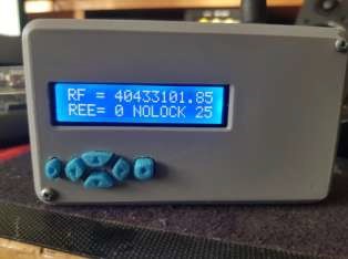
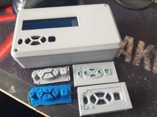
Recently I printed off a box on my 3D printer for an Arduino project, printing off the keys make a hard solid key , However its possible to make your own rubber keys . Normal silicone ( the one that smell like vinegar is best) mix with equal amount of corn flour add food colour ( mix really well colour added allows you to see how well you have mixed) if you wish . Squish into a mold that’s been sprayed with silicon spray ( CRC silicon 808 worked for me) for easy release of the rubber, leave a couple of days to cure and you have nice soft rubber keys that pop with a bit of persuasion out of the mold. Project is the F1CJN rf generator 34.4Mhz to .4Ghz, box was off thingyverse “Mmintbox”
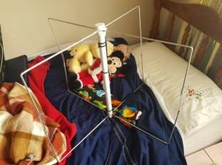
I am also building a 2m Moxon to receive the ISS SSTV pictures. This is right hand circular polarized and made from 4.7mm aluminum rod (3/16th) . The top arms are threaded to 4mm and bolted to plastic conduit and a solder tag added for easy connection to coax. . the arms are connected on the sides by plastic tube as used in aquarium tanks .The phasing harness is 93 ohm coax the stuff that was around a few years back for network cabling . Its a bit hard to find these days but there must be a lot of it in old buildings. Anyhow its all ready for a test just have to wait now for the next ISS sstv to come along.Want to keep a good clock on the PC in your shack? , you can use one of the many on line time clocks to reset your PC but what about when your portable? on the laptop out in the boonies? Im using it for my FT8 and satellite tracking work but useful for any digital modes that require an accurate clock.
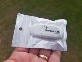
I use one of these cheap USB GPS units from China $6.95 US plus 3.94 postage as of today 13/4/20 . I have used this set up for over a year no issues just stuck the GPS in a click clack type box Silicone the cable hole and sat it on the outside window ledge . The software is free ! working well on my Windows PC . BktTimesync by IZ2BKT
Richard ZL4FZ
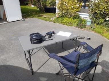
Along with a number of others – some LOTA activity (Lockdown on the Air) as practice for SOTA and also for the Lee Jennings Memorial Activity. Yesterday was a pleasant enough day to take the portable gear outside and setup a temporary antenna as well.
Working on completing a GPS frequency standard. This is a kit from Silicon Chip that uses the 1PPS (Pulse per second) signal from a GPS receiver to “discipline” a TCXO at 40MHz. It then uses this signal very accurate 40MHz signal as the input to a triple PLL IC to generate up to three reference signals for test equipment. After much messing around, the project is acurately adjusting the TCXO, but the GPS receiver will not finally lock to the GPS for position to allow the final adjustments. It appears from the web commentary there may be some issues with the hardware design that may cause a few problems.
And another ‘chapter’ of the replacement study guide for the Amateur Operator Certificate of Competency exam has been written (but yet to be reviewed). This along with several others is an ongoing project making very slow but steady progress.
Michael ZL3AX (J87AB, G0GPX)
I am working on the HamPi project. It is nearly finished, and just ironing out the last few issues. 16 bands possible, 100w, very quiet quality receiver. All the details are at www.hampiradio.com
Mark ZL3JVX
Building a motor controller for a Turbomolecular pump. A big machine with a big name, which creates a whole lot of nothing.
Graeme ZL3FS
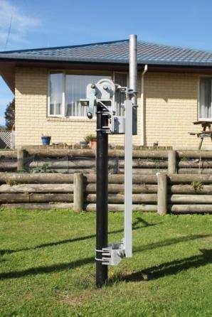
Here is a photo of my latest project I’ve been working on for some time now. It is a pivot for lowering and raising a vertical antenna I’m going to put up. I saw a picture of the pivot in a magazine and thought I’d make one. I’ve yet to get a piece of 50 diameter aluminum tube with 6mm wall that clamps to the piece of protruded fiberglass insulating channel.
The 50mm diameter tube will be 3.5 metres long, u-bolted top and bottom of the fiberglass and the antenna attaches to the top of the tube. (The fiberglass is grey in photos) I had to work out all the dimensions as there were no measurements with the picture. I drew everything up full-sized manually and in isometric to make sure everything fitted together. Not being up to speed on computers and cad drawing systems hence T- squares, set squares etc. were dusted off.
The alloy saddles I machined up to fit 76 mm diameter and 50mm diameter tube. The bottom hinge, the two bolts are made from are 12mm diameter SAFF stainless steel. SAFF is high tensile stainless and it is tough stuff, hard on turning tools especially when screw cutting the threads. I cut the threads on my lathe at home.
The winch mounting plate is 10mm thick mild steel plate, and everything else is in 8mm plate. The post in the ground is carbon steel hollow bar, 76mm diameter, 17mm wall and 1,5 metres concreted into the ground using high strength concrete. You could tie up the Queen Mary !! up to this. I am a a retired toolmaker, fitter machinist.
Any queries phone 381 5468 or email me at this address.
Greg ZL3IX
I’ve just finished a homebrew rig and antenna for 23 cm. Those who attended the Homebrew Evening in February saw it in progress. The transverter and Tx buffer are my
own design, but the PA is the standard 15W module from Mitsubishi.
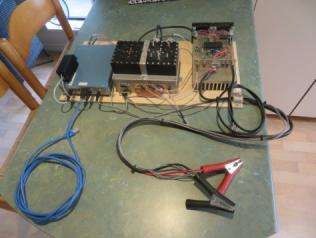
The antenna is a 45-element loop yagi from a combination of the ARRL antenna book and other designs on the Net.
I had the first two QSOs yesterday (Friday April 9) with Ross ZL3RJ and Rod ZL3NW.
Dave ZL3DEM
Over the last few weeks, I have been experimenting with SSTV on 20 meters. A few weeks ago, I installed and familiarised myself with MMSSTV software. I found it here: https://hamsoft.ca/pages/mmsstv.php
I wired the headphone output of the HF rig to the microphone input of the PC. I put a capacitor in series with the signal wire to prevent any DC offset from damaging the HF microphone input.
I then wired the headset output of the PC to the microphone input of the radio. I fed the signal via a 10K pot to reduce the signal strength, thinking that the speaker signal may overload the mics low voltage input. My HF set-up is a little limited, I have an inverted V for 40 meters with a couple of traps for 20 meters.
I’m currently using 20 meters, as 40 tends to send turn the bedside “touch” lights on and off and is very alarming to my children”!
I set the radio to USB – 14.230MHZ and listened. Unfortunately, with the radio connected to the PC there was no sound to be heard for either transmit or receive. Then, by selecting “listen to this device” I was able to hear what the radio was receiving.
Over the following days I tried sending out a CQ image, but with no luck. This weekend, I was in-front of the radio and I received the image below: To which I responded, and I was delighted to receive the following reply:

As you can see, the reply I received included my callsign and my image embedded. This was very exciting!
SSTV is yet another very interesting side to Amateur Radio, and surprisingly active. The MMSSTV software takes a little to get used to. Setting up images and messages was a little fiddly.
There is also a lot of protocols to select, however the software does auto-detect good signals and will tell you what protocol is in use, a little monitoring and I noticed “Scottie 1” & “Scottie 2” were popular.
If you have any questions, I’m a regular at the Branch 05 Tuesday nights, and am happy to discuss my findings, or be further educated by a more experienced SSTV fan.
Next I hope to SSTV simplex 2 meters across town, any takers?
Gilbert ZL3GIL
Project # 1 A bfo for 10.7MHzt which uses a 3.58MHz ceramic resonator. Pulling the frequency down to 3.567MHz and then running it through a tripler creates a 10.7MHz signal source.I then plan to loosely couple the 10.7MHz signal to my Baofeng handheld transceiver thus enabling resolution of the cw from beacons ZL3VHF and ZL3UHF..
Project # 2 Arduino driven VFO Here I’ve tried to create a VFO using an Arduino Nano, an Si5351a breakout board, a 128×64 pixel SPI OLED, and a rotary encoder salvaged from an old computer mouse.
The displays works fine, but the Si5351a draws 400mA on power-up which tells me it didn’t survive one of my 30m experiments from 2018 🙁 Rotary encoder action is yet to be confirmed.
Project # 3 – 10m qrp cw transceiver
I currently have a crystal-locked cw transmitter for 28.060MHz. It pumps out 250mW of RF which is on a par with some Pixie and most Rockmite transceivers I’ve seen. The receiver is also crystal-locked and receives at the same frequency as the tx.
My next step is to combine the two with a suitable rx mute scheme and possibly use just the one crystal for both circuits. Some form of tx/rx offset will also be useful.
Receiver design by Wayne NB6M. Transmitter design by N7KSB. Soldering and wailing by ZL3GIL.
Alan ZL3UYJ
My recent project – a Powerpole distribution box. I’m trying to standardize on Powerpoles for my
13.8V distribution in the shack so I was in need of a distribution box. It also contains a diode bridge voltage dropper so that my FT-817 runs off a lower voltage than 13.8V.
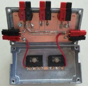
This has allowed me to set up the FT-817 as a more permanent radio in the shack. With the addition of a half wave wire dipole tie-wrapped to a plastic downpipe the FT-817 is now monitoring the Cass Peak repeater on 53.850MHz.


